소아치과 구강수술에서 3D 프린팅 수술 가이드의 적용
Application of 3D-printed surgical guides in pediatric oral surgery
Article information

Trans Abstract
Impacted and supernumerary teeth in pediatric patients may disturb normal eruption and require surgical or orthodontic intervention. This report presents two cases in which three-dimensional-printed surgical guides were used for pediatric oral surgical procedures. In the first case, a 10-year-old boy had an impacted supernumerary tooth associated with eruption disturbance of the mandibular right first premolar. A surgical guide was used to assist the lingual approach and initial bone removal, and spontaneous eruption of the premolar was observed after extraction. In the second case, a 13-year-old boy had a palatally impacted maxillary left canine close to the lateral incisor root. A surgical guide was used for open surgical exposure and button bonding, followed by orthodontic traction. These cases suggest that three-dimensional-printed surgical guides may be useful as an adjunctive tool for confirming the planned surgical approach in pediatric oral surgical procedures involving impacted teeth.
서론
소아·청소년기에는 다양한 국소적 요인으로 인해 치아의 정상적인 맹출이 방해될 수 있으며, 경우에 따라 외과적 또는 교정적 처치가 필요할 수 있다[1]. 특히 병소가 해부학적으로 복잡한 위치에 존재할 경우, 외과적 처치 과정에서 불필요한 골 삭제나 인접치 치근 손상의 위험이 증가할 수 있으므로 정확한 위치 파악과 신중한 수술 계획이 필요하다. 또한 외과적 노출과 교정적 견인이 요구되는 경우, 수술 접근의 정확성과 술식의 예측 가능성은 치료 결과에 중요한 요소가 될 수 있다[2].
최근 콘빔 전산화단층촬영 (cone-beam computed tomography, CBCT)은 매복치와 과잉치의 3차원적 위치 및 인접 구조물과의 관계를 정확하게 평가할 수 있어 진단과 치료계획 수립에 유용하게 활용되고 있다[3]. 또한 구강 스캔 데이터와 CBCT 데이터를 중첩하는 디지털 워크플로우는 치아와 연조직의 표면 정보, 골 내 구조를 함께 반영할 수 있어 보다 정밀한 수술 계획을 가능하게 한다. 이러한 디지털 정보의 통합은 술자가 계획한 접근 경로를 실제 수술 중 참고할 수 있는 3D 프린팅 수술 가이드의 제작으로 이어질 수 있다[4,5].
3D 프린팅 수술 가이드는 임플란트 수술 분야에서 술 전 계획을 수술 과정에 반영하기 위한 도구로 사용되어 왔으며, 최근에는 매복치 발치나 외과적 노출과 같은 구강외과적 술식에도 그 적용 범위가 확대되고 있다[4,6,7]. 특히 소아치과 영역에서는 해부학적 공간이 제한적이고 인접 영구치의 보존이 중요하다는 점에서, 수술 가이드는 계획된 접근 위치와 방향을 확인하는 보조 수단으로 활용될 수 있다[8]. 다만 소아 환자의 매복치 발치 및 외과적 노출에 3D 프린팅 수술 가이드를 적용한 임상 보고는 아직 많지 않다.
이에 본 증례보고에서는 소아치과 환자에서 하악 소구치 맹출장애를 유발한 매복 과잉치의 발치와 상악 구개측 매복 견치의 외과적 노출 및 교정적 견인 과정에 3D 프린팅 수술 가이드를 적용한 두 가지 증례를 보고하고, 그 임상적 활용성을 고찰하고자 한다.
증례
증례 1
10세 남아가 하악 우측 제1소구치 상방의 과잉치와 해당 치아의 맹출장애를 주소로 개인치과의원에서 조선대학교 치과병원 소아치과에 의뢰되었다. 환아의 의과적 병력에서 특이 사항은 없었으며, 하악 우측 제1유구치는 잔존해 있었다. CBCT 결과 하악 우측 제1소구치의 치관과 제2소구치의 치근 사이 설측에 매복 과잉치가 위치한 것으로 확인되었다(Fig. 1). 이에 하악 우측 제1유구치와 과잉치를 발치한 후 하악 제1소구치의 자발적 맹출을 기대하기로 하였다.
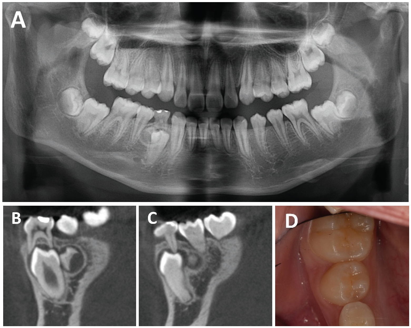
Preoperative radiographs and clinical photograph. Supernumerary tooth associated with eruption disturbance of the mandibular right first premolar is observed. A. Panoramic view at the initial visit. B and C. Sagittal CBCT images at the initial visit. D. Clinical photograph at the initial visit. The mandibular right primary first molar is retained.
3D 프린팅 수술 가이드 제작을 위해 구강 스캐너 (TRIOS 5, 3Shape, Copenhagen, Denmark)를 이용하여 구강 내 스캔을 시행하였다. 이후 3Shape Implant Studio (3Shape, Copenhagen, Denmark)에서 CBCT와 구강 스캔 데이터를 중첩하여 수술 가이드를 설계하였다. 가이드 홀은 매복 과잉치의 위치를 기준으로 설측 초기 접근과 골 삭제 위치를 안내할 수 있도록 설계하였으며, 홀의 직경은 버 접근이 가능한 범위 내에서 약 5 mm로 설정하였다(Fig. 2). 설계된 수술 가이드는 Next-Dent Surgical Guide resin (3D Systems, Rock Hill, USA)을 이용하여 NextDent™ 5100 3D printer (3D Systems, , Rock Hill, USA)로 출력하였으며, 출력 후 수술 전 에틸렌옥사이드 (ethylene oxide, EO) 가스 멸균을 시행하였다.
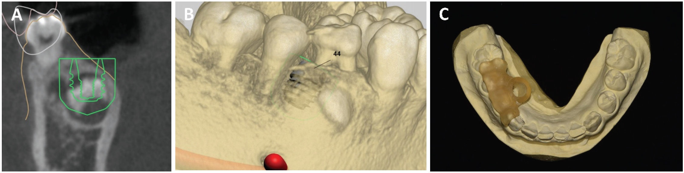
Virtual planning and fabrication of the 3D-printed surgical guide using 3Shape Implant Studio. A. Coronal view. B. Three-dimensional reconstructed view. C. Fabricated 3D-printed surgical guide.
수술 당일 국소마취 하 하악 우측 견치부터 제1대구치까지 설측 판막을 거상한 후 수술 가이드를 적용하여 골 삭제를 시행하였다. 과잉치가 노출되고 일정 수준의 골 삭제가 이루어진 이후에는 수술 가이드를 제거한 뒤 추가적인 골 삭제를 시행하여 과잉치를 발치하였다. 이후 하악 우측 제1소구치의 맹출을 기다리는 동안 인접치의 경사를 막기 위해 band and loop를 장착하였다(Fig. 3).
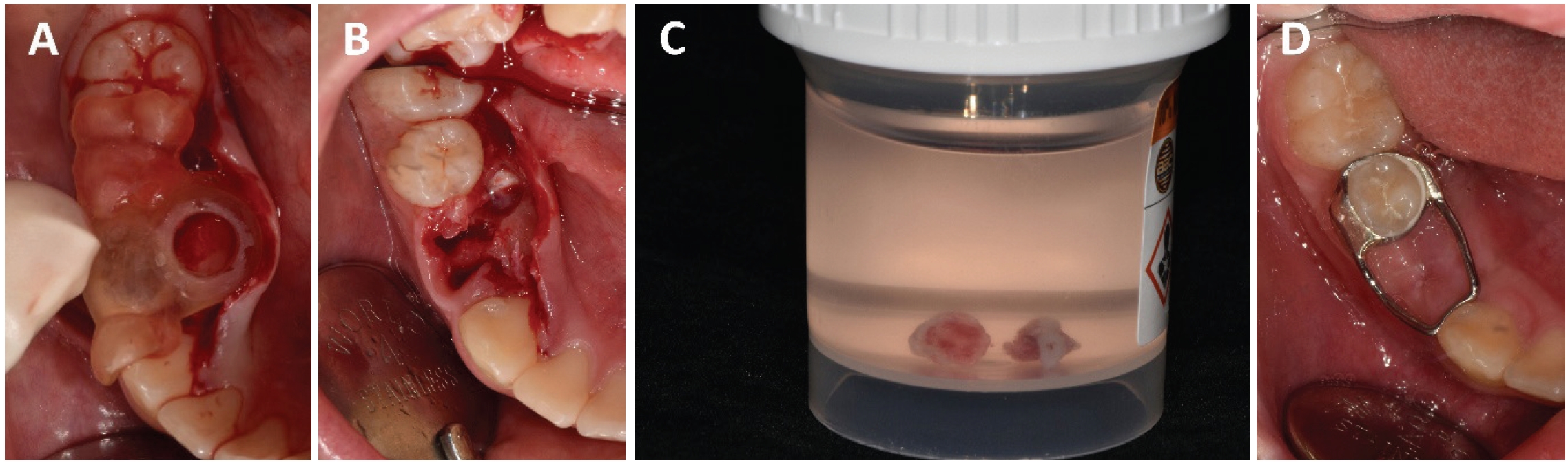
Intraoperative photographs and band and loop placement. A. Seating of the surgical guide after extraction of #84 and lingual flap elevation. B. Sectioning of the supernumerary tooth. C. Extracted supernumerary tooth. D. Band and loop placement after extraction.
9개월 후 촬영한 파노라마 방사선사진에서 하악 우측 제1소구치의 맹출이 확인되었으며 임상적으로 해당 치아의 치관 노출이 확인되어 band and loop를 제거하였다(Fig. 4).
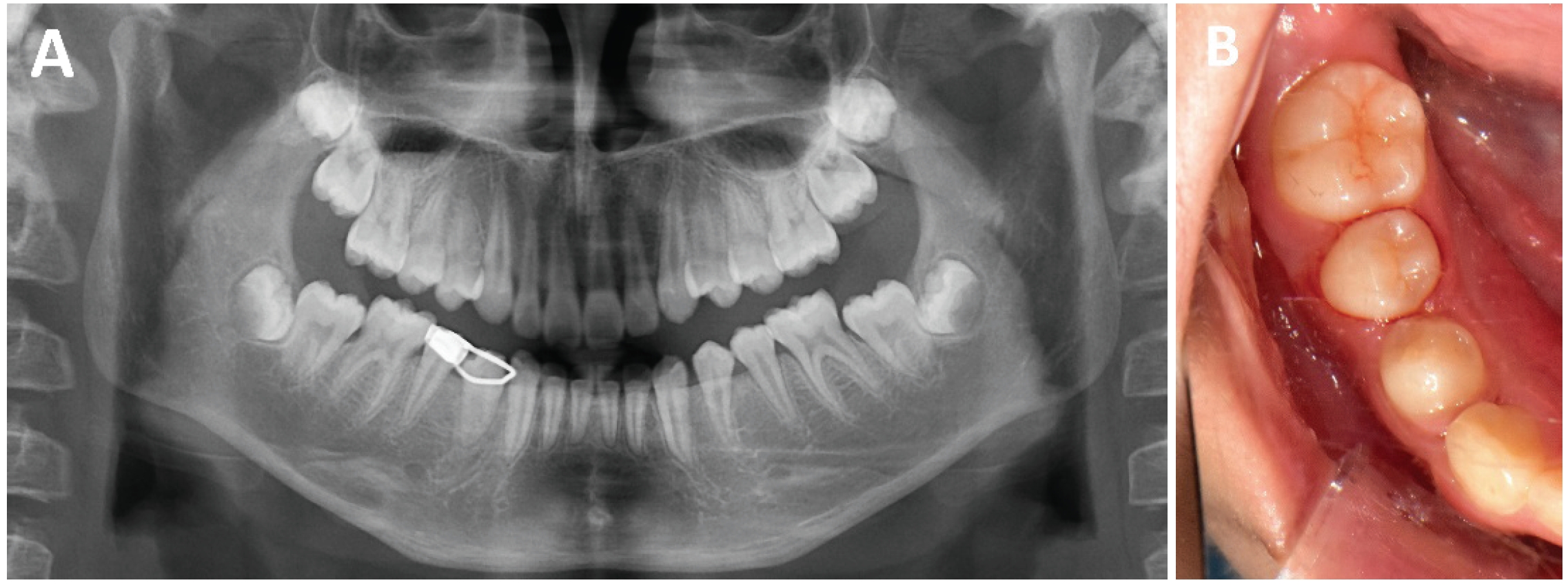
Panoramic radiograph and clinical photograph at 9 months after removal of the supernumerary tooth. A. Panoramic radiograph. B. Clinical photograph.
증례 2
13세 남아가 상악 좌측 견치의 맹출장애를 주소로 조선대학교 치과병원 소아치과에 의뢰되었다. 환아의 의과적 병력에서 특이 사항은 없었다. 임상 검사에서 상악 좌측 유견치가 잔존해 있었으며, 해당 치아는 심한 교모와 잔존치근 상태를 보였고, 하악 전치부는 3전치 양상이었다(Fig. 5). 파노라마 방사선 사진 및 CBCT 촬영 결과, 잔존 상악 좌측 유견치의 치근 흡수와 치근단 방사선투과상이 관찰되었다. 상악 좌측 견치의 치관은 측절치 치근의 구개측에 매복되어 있었으며, 치근 성장은 거의 완료된 상태였다. 인접한 상악 좌측 중절치와 측절치에서 치근 외흡수 소견은 관찰되지 않았다. 측면두부계측방사선사진 분석 결과 경도의 골격성 III급 부정교합 양상을 보였다(Table 1). 또한 양측 제1대구치는 Angle Class I 관계였다(Fig. 6). 환아는 만 7세경 전치부 반대교합으로 개인치과의원에서 1년간 가철식 장치로 교정치료한 병력이 있었다.
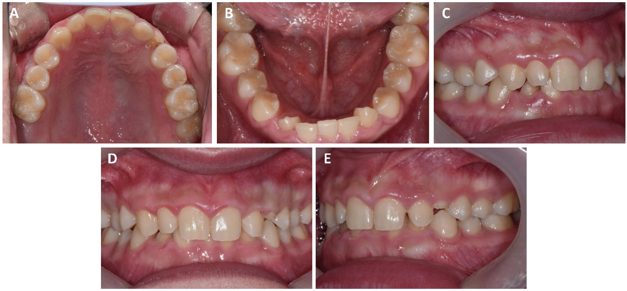
Intraoral photographs at the initial visit.
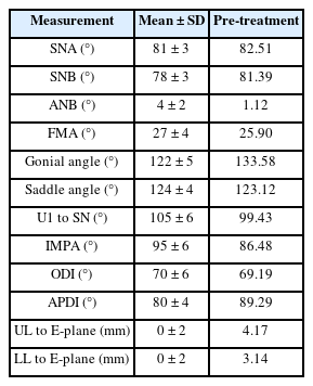
Cephalometric measurements before treatment in Case 2
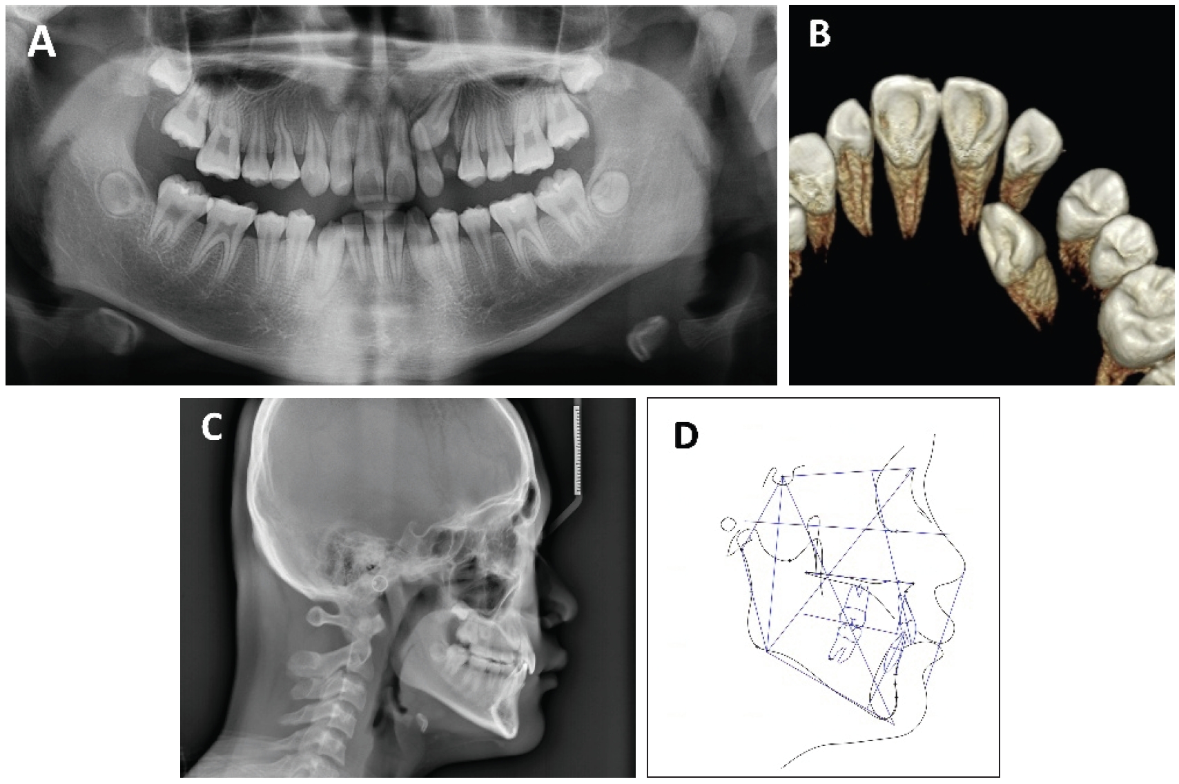
Pre-treatment radiographs and lateral cephalometric tracing. A. Panoramic radiograph. B. Three-dimensional reconstructed occlusal view. C. Lateral cephalometric radiograph. D. Lateral cephalometric tracing.
치료 목표는 매복된 상악 좌측 견치를 교정적으로 견인하여 치열 내에 배열하는 것이었다. 초진 시 상하악 제1대구치가 Class I 관계를 보였고 환아와 보호자가 상악 치열의 배열만을 원했으므로 상악만 교정하기로 하였다. 구개측에 위치한 매복 견치는 치은절제술을 통해 개방형 외과적 노출 (open surgical exposure)로 치관을 노출시킨 후 버튼을 부착하여 원심측으로 견인하고, 이후 견치가 치조정에 근접하면 협측 방향으로 견인하여 치열궁 내 배열을 유도하기로 계획하였다. 수술 과정에서 인접치 치근의 손상을 최소화하기 위해 수술 가이드를 제작하기로 하였다. 3Shape Implant Studio상에서 구강 스캔 데이터와 CBCT를 중첩하여 3D 프린팅 수술 가이드를 설계하였으며, 출력 및 멸균은 첫 번째 증례와 동일한 방식으로 시행하였다. 가이드 홀은 상악 좌측 견치 치관의 구개측 중앙을 향하도록 설계하여, 치관 노출과 견인을 위한 버튼 부착 위치를 안내할 수 있도록 하였다. 홀의 직경은 5 mm로 설정하였고, 구강 내에서 가이드의 적합도를 확인할 수 있도록 전치부와 소구치부에 3개의 창을 형성하였다(Fig. 7).
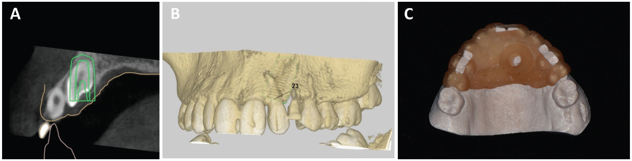
Virtual planning and fabrication of the 3D-printed surgical guide using 3Shape Implant Studio. A. Sagittal view. B. Three-dimensional reconstructed view. C. Fabricated 3D-printed surgical guide.
수술 당일 국소마취 하에 구강 내에 가이드를 적합시킨 후 가이드 홀을 통해 전기소작기를 이용하여 치은절제술을 시행하였다. 견치 치관이 노출된 이후에는 구강 내에서 수술 가이드를 제거한 뒤, 버튼 부착이 가능할 정도까지 견치 주위의 일부 골 삭제와 치은절제술을 시행하여 치관의 구개측에 결찰강선을 연결한 버튼을 부착하였다. 이후 좌측 견치를 제외한 상악 치아에 direct bonding system으로 브라켓을 부착하고, 0.8 mm stainless steel wire를 납착한 변형된 transpalatal arch (modified TPA)를 제작한 후 견치 치관의 결찰강선과 power chain으로 연결하여 원심 견인을 시작하였다(Fig. 8). 향후 견치가 치조정 위치에 근접하면 버튼의 위치를 견치의 협측으로 옮겨 협측 방향으로 견인을 시행할 계획이다.
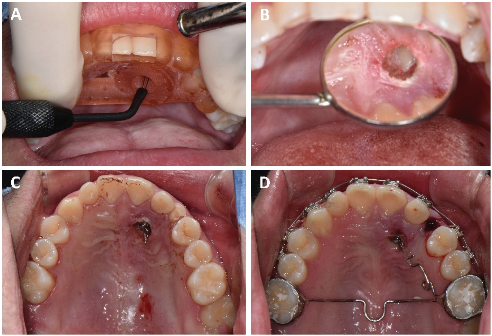
Intraoperative photographs during open exposure and initial traction of the impacted maxillary left canine (#23). A. Gingivectomy was performed using electrocautery after seating of the surgical guide. B. The crown of #23 was exposed. C. A button with an attached ligature wire was bonded to the exposed crown of #23. D. Distal traction was performed using a modified transpalatal arch.
고찰
본 증례보고에서는 소아·청소년 환자에서 매복 과잉치 발치와 매복 견치의 외과적 노출 및 교정적 견인 과정에 3D 프린팅 수술 가이드를 적용하였다. 소아치과 영역에서 매복치와 과잉치는 영구치의 맹출 지연, 이소맹출, 치근 흡수 및 치열궁 공간 문제를 유발할 수 있으며, 특히 혼합치열기에는 계승 영구치의 발육과 맹출이 진행 중이므로 원인 요소의 제거뿐 아니라 인접 영구치와 치조골의 보존, 이후 자발적 맹출 가능성까지 함께 고려해야 한다[1,9,10]. 이러한 점에서 3D 프린팅 수술 가이드는 술식의 방향성을 제공하고, 계획된 접근 위치와 방향을 수술 중 확인하는 데 도움을 줄 수 있는 보조 수단으로 활용될 수 있다[4,8].
이러한 3D 프린팅 수술 가이드는 CBCT에서 얻은 골 내 해부학적 정보와 구강 스캔을 통해 얻은 치아 및 연조직의 표면 정보를 통합하여 제작된다[11]. CBCT는 매복치의 3차원적 위치, 인접치 치근과의 관계, 골 삭제가 필요한 방향과 깊이를 평가하는 데 유용하지만, 영상 정보만으로 실제 구강 내 수술 위치를 정확히 재현하는 데에는 한계가 있다[12]. 구강 스캔 데이터는 치관 형태와 치열궁 표면 정보를 제공하므로, 이를 CBCT와 중첩하면 골 내 매복치와 인접 해부학적 구조의 위치를 구강 내 표면 구조와 연결하여 파악할 수 있다13]. 또한 술 전 계획이 가이드의 형태로 시각화되므로, 경험이 많지 않은 술자에게도 수술 대상 치아와 인접 구조물의 관계를 이해하고 접근 방향을 확인하는 데 도움이 될 수 있다. 실제 본 증례보고의 증례 역시 해당 술식에 대한 경험이 많지 않은 술자가 시행하였고 수술 가이드를 통해 계획한 접근 위치와 방향을 수술 중 확인할 수 있는 보조 수단으로 활용되었다.
본 증례보고에서 3D 프린팅 수술 가이드는 각각 매복 과잉치 발치를 위한 설측 접근과 매복 견치의 외과적 노출을 위한 구개측 접근을 안내하는 데 사용되었다. 첫 번째 증례에서는 매복 과잉치가 하악 우측 제1소구치와 제2소구치 사이 설측 치조 골 내에 위치하고 있어, 과잉치에 접근하기 위해서는 인접 소구치의 치근 및 치관을 피한 제한적인 골 삭제가 필요하였다. 수술 가이드는 초기 접근 방향과 골 삭제 위치를 설정하는 데 도움을 주었고, 과잉치 제거 후 하악 우측 제1소구치의 자발적 맹출이 관찰되었다. 두 번째 증례에서는 상악 좌측 견치가 측절치 치근에 근접한 구개측에 매복되어 있어, 치관을 선택적으로 노출하고 버튼을 부착하기 위해 계획된 위치로 접근하는 것이 중요하였다. 수술 가이드를 이용하여 견치 치관의 구개측 중앙으로 접근하도록 계획함으로써, 계획된 위치에서의 치은절제와 일부 골 삭제를 시행한 후 교정적 견인을 시작할 수 있었다.
수술 가이드를 임상적으로 적절히 활용하기 위해서는 설계 단계에서 가이드의 안정성, 접근 방향, 구강 내 적합도 확인 방법 등을 함께 고려해야 한다. 안정적인 적합을 위해서는 충분한 치아 지지 부위를 포함하는 것이 중요하며, 혼합치열기 환자에서는 치아의 맹출 상태와 동요도에 따라 가이드의 안정성이 달라질 수 있으므로, 가이드 설계 시 안정적인 지지를 제공할 수 있는 치아를 선택하는 것이 중요하다[14,15]. 또한 가이드 홀의 위치, 각도, 직경은 수술 목적에 맞게 설정되어야 하며, 구강 내에서 가이드가 정확하게 적합되었는지 확인할 수 있는 구조도 필요하다. 이를 위해 window를 형성하거나 치아의 일부가 노출되도록 설계하면 수술 중 가이드의 적합도를 확인하는 데 도움이 된다[15-17].
한편, 3D 프린팅 수술 가이드의 정확도는 디지털 워크플로우의 각 단계에 영향을 받는다. CBCT 촬영 시의 환자 움직임, 구강 스캔의 정확도, CBCT와 구강 스캔 데이터의 중첩 오차, 디자인 과정에서의 계획 오차, 프린팅 및 후처리 과정에서의 변형, 그리고 수술 중 가이드의 적합도 등이 최종 정확도에 영향을 줄 수 있다[18]. 특히 소아 환자에서는 협조도, 제한된 개구량, 혼합치열 상태, 유치의 동요도 등이 추가적인 변수로 작용할 수 있다. 따라서 수술 가이드를 적용할 때에는 디지털 계획의 정확성뿐 아니라 실제 구강 내 적합도와 안정성을 확인해야 하며, 가이드가 잘 맞지 않거나 수술 중 움직임이 확인되는 경우에는 무리하게 사용하지 않아야 한다[19].
본 증례들은 소아치과 영역에서 3D 프린팅 수술 가이드가 매복 과잉치 발치와 매복 견치의 외과적 노출 과정에서 계획된 접근 위치와 방향을 확인하는 보조 수단으로 활용될 수 있음을 보여준다. 특히 인접 영구치와의 관계가 복잡하거나 접근 공간이 제한적인 경우, 디지털 수술 가이드는 술 전 계획을 실제 수술 과정에서 참고하고 목표 부위로의 접근을 보조하는 데 도움이 될 수 있다. 따라서 적절한 증례 선택과 신중한 디지털 워크플로우가 전제된다면, 3D 프린팅 수술 가이드는 소아치과 구강수술에서 술 전 계획과 실제 수술 과정을 연결하는 보조적 도구로 활용될 수 있을 것으로 생각된다.
Notes
Conflicts of Interest
None